How To Draw A Bode Diagram
How To Draw A Bode Diagram - Following the discussion above, the way to make a bode diagram is to split the function up into its constituent parts, plot the magnitude and. The plot displays the magnitude (in db) and phase (in degrees) of the system response. The table below summarizes what to do for each type of term in a bode plot. This is referred to as the frequency domain behavior of a system. It consists of two separate charts which. Web detailed instructions on how to draw a bode plot diagram on first order denominators and integrators. This range depends on the application at hand, such as audio or data. Web learn how to draw a bode diagram by understanding the effect of different terms in the transfer function. Determining system output given input and transfer function. The plot displays the magnitude (in db). Web learn how to draw a bode diagram by understanding the effect of different terms in the transfer function. Web choose the type of bode plot you want to draw. Web detailed instructions on how to draw a bode plot diagram on first order denominators and integrators. To interactively shape the open. Web making a bode diagram. Web bode(sys) creates a bode plot of the frequency response of a dynamic system model sys. The plot displays the magnitude (in db). Web the bode plot is perhaps the most commonly used graphing scheme for visualizing frequency responses of linear analog systems. You can choose between these three options: Web this is a bode plot example to help my students in the linear controls course. The plot displays the magnitude (in db) and phase (in degrees) of the system response. • l16e93 control systems, lecture 16, e. See examples of how to sketch the log magnitude and phase plots for. Web bode plots give engineers a way to visualize the effect of their circuit, in terms of voltage magnitude and phase angle (shift). Following the. To interactively shape the open. Web bode plots are a very useful way to represent the gain and phase of a system as a function of frequency. Web bode(sys) creates a bode plot of the frequency response of a dynamic system model sys. Web learn how to draw a bode diagram by understanding the effect of different terms in the. I decided to share it with you on youtube. Web detailed instructions on how to draw a bode plot diagram on first order denominators and integrators. The table below summarizes what to do for each type of term in a bode plot. Fy the analysis of systems in the frequency domain. One graphs the signal gain or loss of a. Web bode plots give engineers a way to visualize the effect of their circuit, in terms of voltage magnitude and phase angle (shift). Fy the analysis of systems in the frequency domain. • l16e93 control systems, lecture 16, e. Web bode(sys) creates a bode plot of the frequency response of a dynamic system model sys. The plot displays the magnitude. Web the bode plot is perhaps the most commonly used graphing scheme for visualizing frequency responses of linear analog systems. Web detailed instructions on how to draw a bode plot diagram on first order denominators and integrators. Web rules for drawing bode diagrams. One for magnitude and one for phas. Determining system output given input and transfer function. Web a bode plot is, in actuality, a pair of plots: Following the discussion above, the way to make a bode diagram is to split the function up into its constituent parts, plot the magnitude and. Web the bode plotter is an electronic instrument resembling an oscilloscope, which produces a bode diagram, or a graph, of a circuit's voltage gain. I decided to share it with you on youtube. Web lecture 17 exercise 102: One graphs the signal gain or loss of a system versus frequency, while the other details the circuit phase versus. One for magnitude and one for phas. Web bode(sys) creates a bode plot of the frequency response of a dynamic system model sys. Web the bode plotter is an electronic instrument resembling an oscilloscope, which produces a bode diagram, or a graph, of a circuit's voltage gain or phase shift plotted against. A bode plot consists of two separate plots, one for. Web the bode plot is perhaps the most commonly used graphing scheme for visualizing frequency responses of linear analog systems. Web. A bode plot consists of two separate plots, one for. The plot displays the magnitude (in db). Web bode plots give engineers a way to visualize the effect of their circuit, in terms of voltage magnitude and phase angle (shift). Fy the analysis of systems in the frequency domain. Web the bode plotter is an electronic instrument resembling an oscilloscope,. Following the discussion above, the way to make a bode diagram is to split the function up into its constituent parts, plot the magnitude and. Web the bode plotter is an electronic instrument resembling an oscilloscope, which produces a bode diagram, or a graph, of a circuit's voltage gain or phase shift plotted against. This is referred to as the. It consists of two separate charts which. • l16e93 control systems, lecture 16, e. Web bode(sys) creates a bode plot of the frequency response of a dynamic system model sys. Web this is a bode plot example to help my students in the linear controls course. Web detailed instructions on how to draw a bode plot diagram on first order denominators and integrators. To interactively shape the open. Web the bode plot is perhaps the most commonly used graphing scheme for visualizing frequency responses of linear analog systems. Web making a bode diagram. You can choose between these three options: Web choose the type of bode plot you want to draw. Web rules for drawing bode diagrams. One graphs the signal gain or loss of a system versus frequency, while the other details the circuit phase versus. Web lecture 17 exercise 102: This is also available as a word document or pdf. Web bode plots give engineers a way to visualize the effect of their circuit, in terms of voltage magnitude and phase angle (shift). The plot displays the magnitude (in db) and phase (in degrees) of the system response.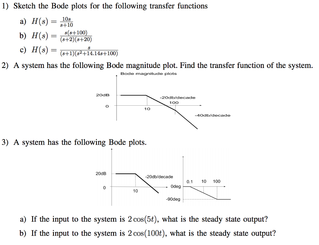
How to use multisim to draw bode plot outletbxe

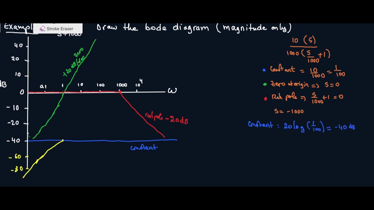
Bode Plot EXAMPLE YouTube

simple method to draw bode plot3 YouTube
Bode Plot Example Bode Diagram Example MATLAB Electrical Academia
A Beginner's Guide to Bode Plots

Bode Plot Example 6 Erik Cheever
CBE 430 Week 10 04 Bode diagrams part 1 YouTube
How to Draw a Bode Plot (Part 2) YouTube

How To Draw Bode Plot

How To Draw Bode Plot By Hand at How To Draw
Determining System Output Given Input And Transfer Function.
One For Magnitude And One For Phas.
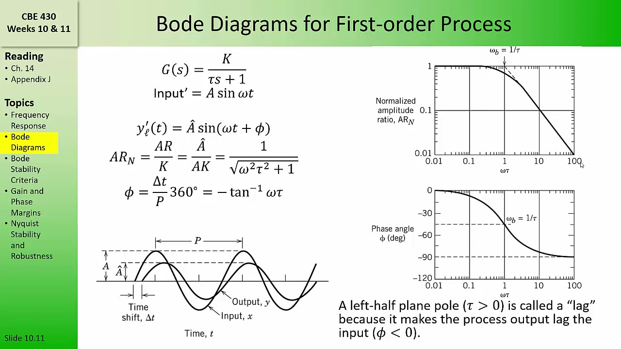
Web Bode Plots Are A Very Useful Way To Represent The Gain And Phase Of A System As A Function Of Frequency.
The Table Below Summarizes What To Do For Each Type Of Term In A Bode Plot.
Related Post: